1848 SEELY Ships Shot Hole Plug – Art 9557
The following information was scanned and read with OCR directly from a copy of the original patent. We apologize for any difficulty in reading the OCR text
- UNITED STATES PATENT OFFICE.
- SAMUEL J. SEELY OF NEW YORK N. Y.
- SHOT-PLUG.
- Specification of Letters Patent No. dated October 10 184
To all whom it may concern:
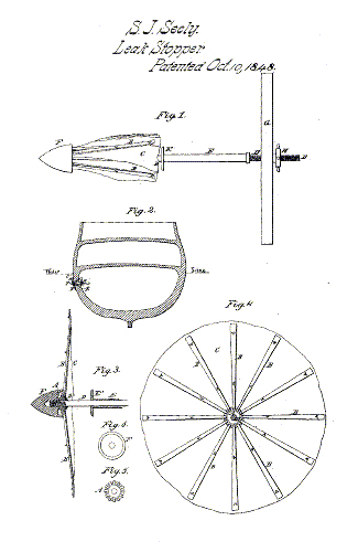
Be it known that I SAniuEn J. SEELY of the city county and State of New York have invented a Shot-Plug for Stopping Leaks in Ships Caused by Shot from the Enemy During an Engagement; which is described as follows reference being had to the annexed drawings of the same making part of this specification. Figure 1 is a view of the plug contracted and ready to be forced through the shot hole from the inside of the ship; to be then expanded and brought over the hole in the manner represented in Figs. 2 3 and 4 to exclude the water. Fig. 2 is a vertical transverse section of a ship pierced with a shot below the water line and the leak stopped by my improved plug which is represented on a small scale as forced through from the inside expanded and made fast by a buckler. screw and wrench. Fig. 3 is a vertical section of the shot plug as expanded ready to be forced back against the side of the vessel. Fig. 4 is a view of the outside of the shot plug in its expanded position the radial hinged springs to which the cloth is secured being represented on the outside of the cloth the conical head being removed from the center in order to show the manner of jointing the springs to the ring. Fig. 5 is a plan of the ring plate detached from the shaft. Fig. 6 is a plan of the under side of the conical head showing the recess in the same to receive circular plate and jointed ends of the springs.
Similar letters in the several figures refer to corresponding parts.
The nature of my invention consists in the formation of a “shot plug” by which a leak caused by a shot from all enemy at any depth below the water line can be effectually stopped in a few seconds from the inside of the vessel said improved “shotplug” being used as a substitute for the ordinary frustrum of a cone plug which is suspended over the side of the ship and applied to the stopping of a leak when near the water line by lowering a man into the sea who inserts the plug and drives it into the shot hole as well as he is able and as quick as possible being all the time exposed to the aim of the sharp shooters in the round top of the enemy’s ship : or as a . substitute for the common ” jackass ” or bag of oakum which is forced into the shot hole from the outside of the ship. Both modes are defective; and many a noble ship has gone to the bottom of the sea for want of an effectual substitute: The use of the conical plug is objectionable not only on account of the difficulty and danger of in’ert iig it during an action but when inserted it has been found insufficient to stop. the leak on account of its conical form not being ‘susceptible of closing an oval or splintered and irregularly formed hole made by a large shot striking the vessel obliquely and when inserted allowing the water- to enter and retarding the motion Of the ship by reason of its projecting several feet beyond the side thereof: When the shot hole is much below the surface of the water the conical plug cannot be inserted from the outside the hole being inaccessable to the carpenter who is lowered over the side of the ship. And when inserted from the inside will not stop the entrance of the water. On account of the plug (which is conical) net fitting the irregularities of the shot hole which is always much. splintered on the inside. The same objection applies to the use of -the “jackass.” My “shot plug” is not liable to any of the’ above named objections and stops the leak effectually in a few seconds and needs no alteration or attention and when the ship arrives in dock it can be removed in a few moments and during the sailing of the vessel does not retard her motion but very slightly and the pressure of the water against the head springs the fearnaught serving to close the latter more effectually as a flap valve over the shot hole and most effectually to exclude the water and being held securely by a buckler and screw. on the inside of the 95 ship sothat is can he tightened at pleasure; requiring only one than in each wing of the ship whereas by the use of the conical plug the whole force of the carpenter’s crew is required to attend to the plugs and pumps during an action.
A is the center plate .or ring made circu la . or many sided of iron or any suitable material to which a number of springs are attached having an opening in its center to admit a shaft over which said plate or ring is slipped. and secured by a head and shoulder on said shaft.
B are ten or more slightly curved radial springs about seven or eight inches in 114 length hinged to the central plate made flat and slightly tapered and widened outwardly toward their extremities which are slightly curved outwardly for the purpose of preventing their catching in the ship’s sides and may be made of any required size number and length to answer the intended purpose. The fearnaught water proof cloth or flexible valve is attached to these springs by wire loops or thread stitches or other suitable means.
C is a circular sheet of fearnaught cloth india rubber or other suitable material for excluding water about eighteen inches diameter or any suitable size to cover the shot hole perforated in the center for the shaft to pass through and secured to the springs in any suitable and effectual way.
D is the central cylindrical shaft which is passed through the center of the fearnaught valve and circular plate to which the springs are hinged and screwed into the conical I head. This shaft is made of iron about two feet long and about or 4 inch in diameter having a screw cut on each end-one of the screws being designed to be screwed into the head and the other to receive the wrench by which the shaft is drawn inward through the buckler. It is reduced in diameter forming a shoulder or collar D’ for the plate to rest on that carries the springs. This collar may be – of greater diameter than the main body of the shaft as represented at D’ in Fig. 3. The fearnaught and washer being placed between the plate A and collar D’.
E is a sliding tube with a beveled flange E’ for expanding the fearnaught valve. This tube is made of copper or other material about 8 or 9 inches in length and a little larger in diameter than the shaft over which it slides back and forth between the fearnaught and buckler. The flange or circular plate E’ for expanding the fearnaught and springs is formed around the end of the tube next the fearnaught and is made of a diameter sufficient to accomplish the intended purpose.
F is the conical head into which the outer end of the shaft is screwed. It is made of cast iron in the shape of a cone or other figure and of sufficient size say about 3 inches diameter and 3i inches in length having a circular cavity in its large end about 4 inches deep by 2:1 inches diameter forming a circular curb or ring for the purpose of receiving and protecting the joints of the springs and forming a shoulder or stop against which the springs strike when expanded as represented in Fig. 3 said shoulder being made slightly beveling on the outer edge.
G is the buckler made of a piece of cord wood broken bar studding sail yard or other article of the like nature which may be conveniently at hand pierced with an inch auger hole through the center for the insertion of the shaft.
H is the wrench or nut screwed on the inner end of the shaft and against the buckler for drawing the fearnaught when expanded against the side of the vessel. It has one or more handles by which it is turned by the carpenter or other person. The plate to which the springs are hinged or jointed may be made octagonal or polygonal let into a recess in a plate or head of any required form having a square or po…